การให้บริการ Internet ในปัจจุบันของผู้ให้บริการในบ้านเราปกติก็จะมี Broadband Internet หรือ เน็ตตามบ้าน และ WiFi Internet ที่ให้บริการตามจุดต่างๆ เช่นในห้าง หน้าเซเว่น หรือตามที่ท่องเที่ยว เป็นต้น
จากบทความที่แล้วที่แล้วเราพูดถึง Broadband Internet และการคอนฟิก BNG คราวนี้เราจะเพิ่ม IPoE เข้าไปด้วย การให้บริการ WiFi Internet จะใช้โปรโตคอล IPoE ในการขอสิทธิเข้าใช้งานเครือข่ายระหว่าง Client เช่น มือถือ โน๊ตบุ๊ค กับ BNG ( Broadband Network Gateway )
ในแล็บนี้ประกอบไปด้วย
- PC Client เพื่อใช้ในการขออนุญาตเข้าใช้งานเครือข่ายทั้งแบบ PPPoE และ IPoE
- ISP Transmission เพื่อรับส่งข้อมูลระหว่าง Client กับ BNG. โดย Implement เป็น MPLS L2VPN ประกอบไปด้วย Router หลายๆ ยี่ห้อเช่น Cisco, Huawei, Juniper และ Nokia เป็นต้น
- NOKIA BNG เพื่อให้บริการ Internet ด้วย PPPoE และ IPoE โปรโตคอล. ในแล็บนี้ BNG จะทำเป็น MPLS L2VPN ด้วย
- RADIUS. ในแล็บนี้ใช้ PC แล้ว Run Program Tek RADIUS LT เพื่อทำเป็น External RADIUS เก็บ User/Pass และ Profile( package internet ) ของ User
- Juniper SRX ทำหน้าที่เป็น Firewall คั่นระหว่าง BNG, Radius และ Internet
- NAT-PC ทำหน้าที่ NAT Subscriber เพื่อให้ออก Internet ได้จริง
Network Diagram
ผมจะขออธิบายทีละส่วนตามนี้นะครับ
1. IPoE Call Flow
2. EVE-NG Lab Diagram
3. การคอนฟิก NOKIA ฺBNG เพื่อให้บริการ PPPoE และ IPoE
4. การคอนฟิก Firewall Juniper SRX
5. การสร้าง RADIUS ด้วย Tek RADIUS Lite
6. การคอนฟิก NAT-PC เพื่อให้ Subscriber ออก Internet ได้
7. ISP Transmission Network Diagram
8. NOKIA BNG คอนฟิก OSPF MPLS-LDP
9. Cisco คอนฟิก OSPF MPLS-LDP
10. Juniper vMX คอนฟิก OSPF MPLS-LDP
11. Huawei คอนฟิก OSPF MPLS-LDP
12. Juniper Olive คอนฟิก OSPF MPLS-LDP
13. การคอนฟิก MPLS L2VPN VLL ที่ NOKIA, Cisco และ Huawei.
14. แสดงสถานะ OSPF neighbor , LDP session ของแต่ละ Router
15. IPoE Client Authentication และทดสอบออก Internet
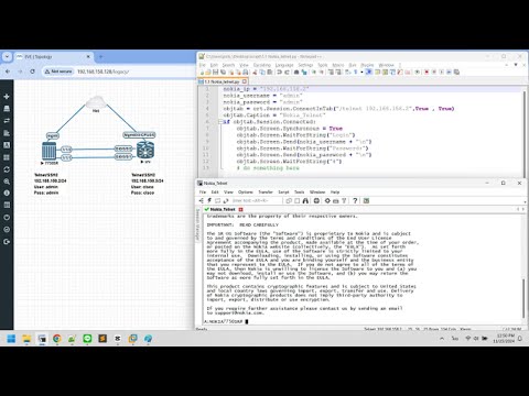
16. PPPoE Client Authentication และทดสอบออก Internet
17. NOKIA BNG แสดงสถานะ IPoE/PPPoE session และสถานะการแจก IP ของ DHCP.
18. ผล Capture Traffic IPoE
19. ผล Capture Traffic PPPoE
20. ข้อมูล Version
1. IPoE Protocol
IPoE Authentication ด้วย DHCP Protocol. ระบุตัวตนด้วย MAC Address. ปกติการให้บริการ WiFi Internet ของผู้ให้บริการจะเป็น Open Security คือสามารถขออนุญาตเข้าได้เลย แต่จะบังคับให้ User Redirect เข้าหน้า Portal เพื่อล๊อกอินอีกที แต่ในแล็บนี้จะให้ User ใช้ Internet ได้เลย (ใจดี ^^).
Flow ของ IPoE ไม่ขอพูดถึงรายละเอียดนะครับ ดูจาก IPoE Call Flow ตามรูปด้านล่าง

2. EVE-NG Lab Diagram
หน้าตา LAB EVE-NG ส่วนการ Virtual Router ดูรายละเอียดตามลิ้งค์นี้เลยครับ https://www.eve-ng.net/index.php/documentation/howtos/

3. การคอนฟิก NOKIA ฺBNG เพื่อให้บริการ PPPoE และ IPoE
ในแล็บนี้จะใช้ Nokia 7750SR โดยแยก CPM (การ์ด control ) กับ IOM ( ไลน์การ์ด) ออกจากกัน และเนื่องจาก BNG ทำต้องทำ L2VPN (Epipe) ด้วย แต่ใน Group-Interface ต้องผูกกับ Physical Interface จึงต้องทำ Physical Loop (1/1/6 - 1/1/5) มาช่วยในการรับส่งข้อมูลจาก Epipe (1/1/6) มาเข้า Group-Interface ( 1/1/5). ใช้ Bridge Cloud ของ EVE-NG ช่วยในการทำ Loop.
3.1 NOKIA BNG การคอนฟิก Radius Server Policy
Configure Loopback interface เพื่อเป็น Source Address ในการติดต่อกับ RADIUS. Radius Server Policy สามารถมีได้มากกว่า 1 Radius เพื่อทำ Redundant. ในแล็บนี้ใช้ Radius ตัวเดียว.
A:BNG#/configure service vprn 100
A:BNG>config>service>vprn# info
----------------------------------------------
            interface "loopback_radius" create
                address 10.5.4.1/32
                loopback
            exit
            radius-server
                server "radius1" address 10.5.5.10 secret abc123 create
                    description "Radius1"
                exit
            exit
----------------------------------------------

A:BNG#/configure aaa
A:BNG>config>aaa# info
----------------------------------------------
        radius-server-policy "RADIUS_SERVER_1" create
            servers
                router 100
                source-address 10.5.4.1
                server 1 name "radius1"
            exit
        exit
----------------------------------------------
3.2 NOKIA BNG การคอนฟิก Authentication and Accounting Policy
Authentication Policy เพื่อกำหนด Parameters ที่ใช้ในการ Authentication กับ Radius. ในแล็บนี้จะแยกกันระหว่าง IPoE กับ PPPoE.Accounting Policy เพื่อส่งข้อมูลของ User Update ให้ Radius เป็นระยะๆ ( Interim )
A:BNG#/configure subscriber-mgmt
A:BNG>config>subscr-mgmt# info
----------------------------------------------
        authentication-policy "AUTHEN-IPOE" create
            radius-server-policy "RADIUS_SERVER_1"
        exit
        authentication-policy "AUTHEN-PPPOE" create
            pppoe-access-method pap-chap
            radius-server-policy "RADIUS_SERVER_1"
        exit
        radius-accounting-policy "RADIUS-ACCOUTING" create
            include-radius-attribute
                calling-station-id mac
                subscriber-id
                user-name
                std-acct-attributes
            exit
            session-id-format number
            radius-server-policy "RADIUS_SERVER_1"
        exit
3.3 NOKIA BNG การคอนฟิก sla-profile, sub-profile และ sub-indent-policy
sla-profile ปกติจะมีคอนฟิก QoS เพื่อควบคุม Bandwidth ( Speed ) ของลูกค้า และ IP-Filter เพื่อ Redirect หน้าเว็บของ User แต่ในแล็บนี้สร้างไว้เฉยๆ ไม่ได้ควบคุมอะไรเลย
sub-profile ก็จะมีคอนฟิกส่วนของ Accounting เพื่ออัพเดทของมูลของ subscriber ให้ Radius
sub-ident-policy เอาไว้ map ค่า sla-profile ,sub-profile ที่ส่งมาจาก Radius กับ คอนฟิกใน BNG ( ค่าที่ส่งมาจาก radius กับ ที่สร้างไว้ไม่ตรงกันก็ได้ แต่แนะนำว่าคอนฟิกให้ตรงกันจะดีกว่า เพื่อความสะดวกในการจัดการและการทำความเข้าใจ )
A:BNG# configure subscriber-mgmt
A:BNG>config>subscr-mgmt# info
----------------------------------------------
        sla-profile "DEFAULT-SLA-IPOE" create
        exit
        sla-profile "DEFAULT-SLA-PPPOE" create
        exit
        sub-profile "DEFAULT-SUB-IPOE" create
        exit
        sub-profile "DEFAULT-SUB-PPPOE" create
        exit
        sla-profile "SLA-IPOE-PKG-1" create
        exit
        sla-profile "SLA-PPPOE-10M" create
        exit
        sub-profile "SUB-IPOE-PKG-1" create
            radius-accounting
                policy "RADIUS-ACCOUTING"
            exit
        exit
        sub-profile "SUB-PPPOE-10M" create
            radius-accounting
                policy "RADIUS-ACCOUTING"
            exit
        exit
        sub-ident-policy "SUB-INDENT" create
            sub-profile-map
                use-direct-map-as-default
            exit
            sla-profile-map
                use-direct-map-as-default
            exit
        exit
----------------------------------------------
3.4 NOKIA BNG การคอนฟิก Local DHCP Server
DHCP Server สามารถเป็น External หรือ Internal ก็ได้ ในแล็บนี้ใช้เป็น Internal DHCP Server และสร้างแยกกันระหว่าง IPoE กับ PPPoE โดย
IPoE แจก IP วง 172.16.1.0/24 ให้กับ subscriber
PPPoE แจก IP วง 172.16.2.0/24 ให้กับ subscriber
A:BNG# configure service vprn 100
A:BNG>config>service>vprn# info
----------------------------------------------
            dhcp
                local-dhcp-server "DHCP-SERVER-IPOE" create
                    use-gi-address scope pool
                    pool "POOL-IPOE-1" create
                        options
                            dns-server 8.8.8.8
                        exit
                        subnet 172.16.1.0/24 create
                            options
                                default-router 172.16.1.1
                            exit
                            address-range 172.16.1.2 172.16.1.254
                        exit
                    exit
                    no shutdown
                exit
                local-dhcp-server "DHCP-SERVER-PPPOE" create
                    use-gi-address scope pool
                    pool "POOL-PPPOE-1" create
                        options
                            dns-server 8.8.4.4
                        exit
                        subnet 172.16.2.0/24 create
                            options
                                default-router 172.16.2.1
                            exit
                            address-range 172.16.2.2 172.16.2.254
                        exit
                    exit
                    no shutdown
                exit
            exit
            interface "loopback_DHCP-IPOE" create
                address 100.100.100.1/32
                local-dhcp-server "DHCP-SERVER-IPOE"
                loopback
            exit
            interface "loopback_DHCP-PPPOE" create
                address 100.100.100.2/32
                local-dhcp-server "DHCP-SERVER-PPPOE"
                loopback
            exit
----------------------------------------------
3.5 NOKIA BNG คอนฟิก Subcriber-Interface และ Group-Interface
Subscriber-Interface เป็น Interface ที่เอาไว้คุยกับ Subscriber Host มีคอนฟิก address เพื่อเป็น ip-gateway ของ subscriber
Group-interface จะเป็น interface ที่ผูกกับ physical interface (1/1/5) และเป็นตัวกำหนด parameter ต่างๆ ของ subscriber ที่จะเข้ามาทาง interface นี้เช่น Authentication และ DHCP
A:BNG#configure service vprn 100
A:BNG>config>service>vprn# info
----------------------------------------------
            subscriber-interface "SUB-IPOE" create
                address 172.16.1.1/24
                group-interface "GRP-IPOE-1" create
                    dhcp
                        server 100.100.100.1
                        trusted
                        lease-populate 131071
                        gi-address 172.16.1.1
                        no shutdown
                    exit
                    authentication-policy "AUTHEN-IPOE"
                    sap 1/1/5:10 create
                        sub-sla-mgmt
                            def-sub-id use-auto-id
                            def-sub-profile "DEFAULT-SUB-IPOE"
                            def-sla-profile "DEFAULT-SLA-IPOE"
                            sub-ident-policy "SUB-INDENT"
                            multi-sub-sap 131071
                            no shutdown
                        exit
                    exit
                exit
            exit
            subscriber-interface "SUB-PPPOE" create
                address 172.16.2.1/24
                group-interface "GRP-PPPOE-1" create
                    dhcp
                        server 100.100.100.2
                        trusted
                        lease-populate 131071
                        client-applications ppp
                        gi-address 172.16.2.1
                        no shutdown
                    exit
                    authentication-policy "AUTHEN-PPPOE"
                    sap 1/1/5:20 create
                        sub-sla-mgmt
                            def-sub-id use-auto-id
                            def-sub-profile "DEFAULT-SUB-PPPOE"
                            def-sla-profile "DEFAULT-SLA-PPPOE"
                            sub-ident-policy "SUB-INDENT"
                            multi-sub-sap 131071
                            no shutdown
                        exit
                    exit
                    pppoe
                        session-limit 131071
                        sap-session-limit 131071
                        no shutdown
                    exit
                exit
            exit
----------------------------------------------
3.6 NOKIA BNG คอนฟิกให้ BNG ต่อกับ Internet และ Radius
เพื่อที่จะให้ Subcriber ออก Internet ได้ BNG ต้องมีทางออก Internet. ในแล็บนี้ BNG คอนฟิก OSPF กับ Juniper SRX. โดย Juniper SRX จะประกาศ Default Route และ RADIUS Route มาให้ BNG. ส่วน BNG จะประกาศ Subscriber IP Address และ loopback_radius ออกไป.
A:BNG# configure service vprn 100
A:BNG>config>service>vprn# info
----------------------------------------------
            interface "to_vSRX" create
                address 192.168.12.1/24
                ip-mtu 1500
                sap 1/1/1 create
                exit
            exit
            ospf 10.5.4.1
                area 0.0.0.0
                    interface "loopback_radius"
                        passive
                        no shutdown
                    exit
                    interface "to_vSRX"
                        interface-type point-to-point
                        no shutdown
                    exit
                    interface "SUB-IPOE"
                        passive
                        no shutdown
                    exit
                    interface "SUB-PPPOE"
                        passive
                        no shutdown
                    exit
                exit
                no shutdown
            exit
----------------------------------------------
4. การคอนฟิก Firewall Juniper SRX
Juniper SRX เป็น firewall ที่คั่นระหว่าง BNG , RADIUS และ Internet. โดยแบ่งแต่ละส่วนออกเป็น Zone และ Run OSPF กับ BNG. รายละเอียดดูจาก Diagram ด้านล่าง
Juniper SRX คอนฟิก interface
[edit interfaces]
set interfaces ge-0/0/0 unit 0 family inet address 192.168.253.1/24
set interfaces ge-0/0/1 unit 0 family inet address 10.5.5.1/24
set interfaces ge-0/0/2 unit 0 family inet address 192.168.12.2/24
Juniper SRX คอนฟิก security zone , map port เข้า zone และ allow ping เพื่อเอาไว้ปิงเทส
[edit security zones]
set security zones security-zone trust interfaces ge-0/0/1.0 host-inbound-traffic system-services ping
set security zones security-zone untrust interfaces ge-0/0/0.0 host-inbound-traffic system-services ping
set security zones security-zone SUBSCIBER_ZONE interfaces ge-0/0/2.0 host-inbound-traffic protocols ping
set security zones security-zone SUBSCIBER_ZONE interfaces ge-0/0/2.0 host-inbound-traffic protocols ospf
Juniper SRX คอนฟิก Routing Protocol
คอนฟิก static default route ออกไปทาง NAT-PC เพื่อออก Internet และ Redistribute เข้า OSPF
คอนฟิก OSPF และ enable interface ที่ต่อไป BNG Radius และ NAT PC
[edit routing-options]
set routing-options static route 0.0.0.0/0 next-hop 192.168.253.2

[edit protocols ospf]
set protocols ospf export OSPF-EXPORT
set protocols ospf area 0.0.0.0 interface ge-0/0/2.0 interface-type p2p
set protocols ospf area 0.0.0.0 interface ge-0/0/1.0 passive
set protocols ospf area 0.0.0.0 interface ge-0/0/0.0 passive

[edit policy-options]
set policy-options policy-statement OSPF-EXPORT term term1 from protocol static
set policy-options policy-statement OSPF-EXPORT term term1 then accept
Juniper SRX คอนฟิก Security policy
เพื่ออนุญาตให้ BNG คุยกับ Radius และ อนุญาตให้ Subscriber ออก Internet ได้. ในแล็บนี้ SRX จะอนุญาตทั้งหมด ไม่มีบล๊อกอะไรเลย (แล้วจะมีทำไม อิอิ เอาไว้แล๊บหน้าๆๆๆค่อยมาบล๊อกละกันครับ)
[edit security policies]
set security policies from-zone SUBSCIBER_ZONE to-zone untrust policy To-Internet match source-address any
set security policies from-zone SUBSCIBER_ZONE to-zone untrust policy To-Internet match destination-address any
set security policies from-zone SUBSCIBER_ZONE to-zone untrust policy To-Internet match application any
set security policies from-zone SUBSCIBER_ZONE to-zone untrust policy To-Internet then permit
set security policies from-zone SUBSCIBER_ZONE to-zone trust policy Policy-1 match source-address any
set security policies from-zone SUBSCIBER_ZONE to-zone trust policy Policy-1 match destination-address any
set security policies from-zone SUBSCIBER_ZONE to-zone trust policy Policy-1 match application any
set security policies from-zone SUBSCIBER_ZONE to-zone trust policy Policy-1 then permit
5. การสร้าง RADIUS ด้วย Tek RADIUS LT
ในแล็บนี้ใช้ Tek RADIUS LT เพื่อทำเป็น RADIUS Server. ดาวน์โหลดได้จากลิ้งค์นี้ https://www.kaplansoft.com/download.html (version 5.5.4 ยิง CoA ได้ด้วยนะ แล็บนี้ใช้ version 5.5.3 )5.1 Tek Radius คอนฟิก IP และเพิ่ม NAS
เพื่ออนุญาตให้ BNG (10.5.4.1 ) คุยกับ RADIUS ได้ โดยใช้ password เป็น abc123 ตามรูป

5.2 Tek RADIUS เพิ่ม Radius Attribute
RADIUS กับ BNG ต้องคุยกันด้วย Attribute เดียวกัน ( ถ้า RADIUS Attribute ไม่ตรงกันก็ต้องแปลงด้วย python script แล็บหน้าๆนะครับ) โดย Tek RADIUS LT ที่ดาวน์โหลดมา จะไม่มี Nokia Radius Attribute ( Nokia รวมบริษัทกับ Alcatel แล้วแต่ชื่อ Radius Attribute ยังเป็น Alcatel อยู่) ต้องเพิ่ม Attribute เข้าไป โดยไปที่ Tab Dictionary Editor

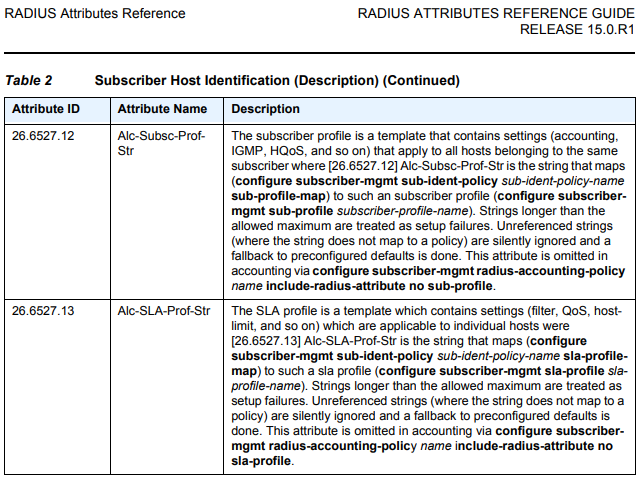
5.3 NOKIA RADIUS ATTRIBUTE REF
สำหรับ Nokia Radius Attribute ที่จะใช้ในแล็บมี 2 อย่างคือ Alc-Subsc-Prof-Str กับ Alc-SLA-Prof-Str ส่วน attribute อื่นๆ สามารถศึกษาเพิ่มเติมได้จาก ลิ้งค์นี้ https://documentation.nokia.com/cgi-bin/dbaccessfilename.cgi/3HE11975AAAATQZZA01_V1_7750%20SR%20RADIUS%20Attributes%20Reference%20Guide%20R15.0.R1.pdf
5.4 Tek RADIUS กำหนด Username/Password สำหรับ Authentication
IPoE authentication ด้วย MAC. User name ก็จะเป็น MAC ของ IPoE Client. เมื่อ Authentication ผ่าน Radius จะส่งค่า sla-profile: SLA-IPOE-PKG-1, sub-profile: SUB-IPOE-PKG-1 ไปให้ BNG
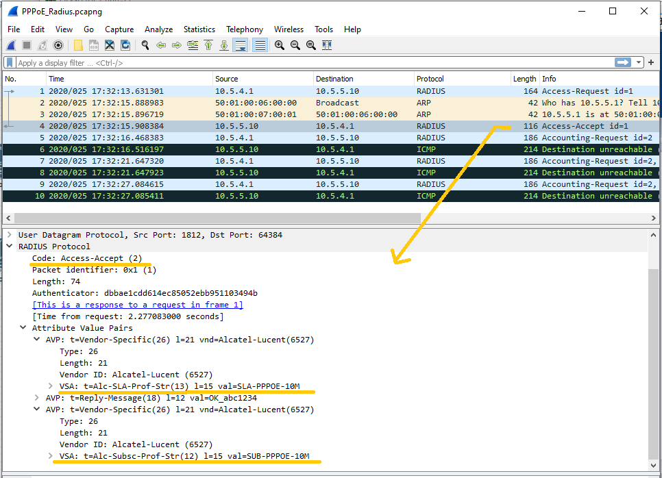
PPPoE authentication ด้วย Username/Password โดยตั้งเป็น bnet1@abc.com/abc1234 เมื่อ Authentication ผ่านแล้ว ก็จะส่งค่า sla-profile: SLA-PPPOE-10M, sub-profile: SUB-PPPOE-10M ไปให้ BNG
จะเห็นว่า sla-profile กับ sub-profile มีคอนฟิกอยู่แล้วที่ BNG

6 การคอนฟิก NAT-PC เพื่อให้ Subscriber ออก Internet ได้
Local Area Connection จะต่อกับ Management Clond ของ EVE-NG. Port นี้จะได้รับจากแจก IP จาก Router จริงที่บ้านและ Share Internet ให้กับ Local Area Connection 2Local Area Connection 2 ต่อกับ Juniper SRX
ต้องทำ Routing เพิ่มเพื่อให้ NAT-PC ส่งข้อมูลกลับไปหา Subscriber ได้ถูกทาง โดยใช้ Cmd run as Adminstrator จากนั้นคอนฟิกเพิ่ม Route ด้วย command line ตามรูปด้านล่าง จากนั้นก็แสดง Route table ด้วย command: route print -4

จบไปแล้วสำหรับฝั่ง Internet และ Radius คราวนี้มาทางฝั่ง Transmission และ Subscriber กันบ้าง
7 ISP Transmission Network Diagram
ในแล็บนี้ ISP Transmission ทำเป็น MPLS L2VPN แบบ Virtual Lease Line ( VLL ) มี Router Cisco กับ Huawei เป็น Provider Edge (PE) ของฝั่ง Subscriber. ส่วน NOKIA BNG ก็เป็นส่วนหนึ่งของ MPLS โดเมนโดยเป็น PE เหมือนกัน. ส่วน Juniper จะเป็น transit routerใช้ LDP เพื่อเป็น Signalling protocol ทั้ง Transport Label และ VPN label
ใช้ OSPF เพื่อทำ Routing Protocol ภายในโดนเมนนี้
ISP Transmission Network Diagram

Huawei eNSP
Router Huawei ไม่สามารถ run ได้นอกตัวโปรแกรม eNSP. ในแล็บนี้จึงใช้ Window แล้วลงโปรแกรม eNSP แล้วใช้เทคนิคการทำ Port Binding เพื่อ Connect กับ Router ตัวอื่นๆ รวมถีง IPoE Client.
โปรแกรม eNSP และ ตัวอย่าง Port Binding ดูได้จากรูปด้านล่างนี้

8. NOKIA BNG คอนฟิก OSPF MPLS-LDP
A:BNG#admin display-config
#--------------------------------------------------
echo "Port Configuration"
#--------------------------------------------------
    port 1/1/2
        description "to_vMX_em2"
        ethernet
            mtu 9212
        exit
        no shutdown
    exit
    port 1/1/3
        description "To_Juniper_Olive_em2"
        ethernet
            mtu 9212
        exit
        no shutdown
    exit
    port 1/1/5
        description "PhyLoop_Grp-int"
        ethernet
            mode access
            encap-type dot1q
            mtu 9212
        exit
        no shutdown
    exit
    port 1/1/6
        description "PhyLoop_EPIPE"
        ethernet
            mode access
            encap-type dot1q
            mtu 9212
        exit
        no shutdown
    exit
exit

A:BNG# /configure router
A:BNG>config>router# info
#--------------------------------------------------
echo "IP Configuration"
#--------------------------------------------------
        interface "system"
            address 10.10.10.1/32
            no shutdown
        exit
        interface "to_Olive"
            address 192.168.16.1/24
            port 1/1/3
            ip-mtu 1500
            no shutdown
        exit
        interface "to_vMX"
            address 192.168.14.1/24
            port 1/1/2
            ip-mtu 1500
            no shutdown
        exit
#--------------------------------------------------
echo "OSPFv2 Configuration"
#--------------------------------------------------
        ospf 0
            area 0.0.0.0
                interface "system"
                    no shutdown
                exit
                interface "to_Olive"
                    interface-type point-to-point
                    no shutdown
                exit
                interface "to_vMX"
                    interface-type point-to-point
                    no shutdown
                exit
            exit
            no shutdown
        exit
#--------------------------------------------------
echo "LDP Configuration"
#--------------------------------------------------
        ldp
            interface-parameters
                interface "to_Olive" dual-stack
                    ipv4
                        no shutdown
                    exit
                    no shutdown
                exit
                interface "to_vMX" dual-stack
                    ipv4
                        no shutdown
                    exit
                    no shutdown
                exit
            exit
            targeted-session
                peer 10.10.10.3
                    no shutdown
                exit
                peer 10.10.10.5
                    no shutdown
                exit
            exit
            no shutdown
        exit
----------------------------------------------
9. Cisco คอนฟิก OSPF MPLS-LDP
Router#show running-config
Building configuration...
!
mpls label protocol ldp
mpls ldp neighbor 10.10.10.1 targeted ldp
!
interface Loopback0
 ip address 10.10.10.3 255.255.255.255
 ip ospf 1 area 0
!
interface FastEthernet0/1
 description "To_vMX_em3"
 ip address 192.168.34.3 255.255.255.0
 ip ospf network point-to-point
 ip ospf 1 area 0
 duplex auto
 speed auto
 mpls ldp discovery transport-address 10.10.10.3
 mpls label protocol ldp
 mpls ip
!
interface FastEthernet2/0
 description "To_Huawei_e1(GE0/0/1)"
 no switchport
 ip address 192.168.35.3 255.255.255.0
 ip ospf network point-to-point
 ip ospf 1 area 0
 mpls ldp discovery transport-address 10.10.10.3
 mpls label protocol ldp
 mpls ip
!
router ospf 1
 router-id 10.10.10.3
 log-adjacency-changes
!
mpls ldp router-id Loopback0 force
!
Router#
10. Juniper vMX คอนฟิก OSPF MPLS-LDP
lab@vMX-1#
[edit interfaces]
set interfaces em2 unit 0 family inet address 192.168.14.4/24
set interfaces em2 unit 0 family mpls
set interfaces em3 unit 0 family inet address 192.168.34.4/24
set interfaces em3 unit 0 family mpls
set interfaces em4 unit 0 family inet address 192.168.46.4/24
set interfaces em4 unit 0 family mpls
set interfaces lo0 unit 0 family inet address 10.10.10.4/32
set interfaces lo0 unit 0 family mpls

[edit protocols]
set protocols mpls interface all
set protocols ospf area 0.0.0.0 interface em2.0 interface-type p2p
set protocols ospf area 0.0.0.0 interface lo0.0 passive
set protocols ospf area 0.0.0.0 interface em3.0 interface-type p2p
set protocols ospf area 0.0.0.0 interface em4.0 interface-type p2p
set protocols ldp interface em2.0
set protocols ldp interface em3.0
set protocols ldp interface em4.0
set protocols ldp interface lo0.0
11. Huawei คอนฟิก OSPF MPLS-LDP
[Huawei]display current-configuration
#
mpls lsr-id 10.10.10.5
mpls
 label advertise non-null
#
mpls l2vpn
#
mpls ldp
#
mpls ldp remote-peer to_bng
 remote-ip 10.10.10.1
#
interface GigabitEthernet0/0/1
 description "To_Cisco3725_fa2/0"
 ip address 192.168.35.5 255.255.255.0
 ospf network-type p2p
 ospf enable 1 area 0.0.0.0
 mpls
 mpls ldp
#
interface GigabitEthernet0/0/2
 description "To_Juniper_Olive_em0"
 ip address 192.168.56.5 255.255.255.0
 ospf network-type p2p
 ospf enable 1 area 0.0.0.0
 mpls
 mpls ldp
#
interface LoopBack0
 ip address 10.10.10.5 255.255.255.255
 ospf enable 1 area 0.0.0.0
#
ospf 1 router-id 10.10.10.5
 area 0.0.0.0
#
12. Juniper Olive คอนฟิก OSPF MPLS-LDP
[edit interfaces]
set interfaces em0 unit 0 family inet address 192.168.56.6/24
set interfaces em0 unit 0 family mpls
set interfaces em1 unit 0 family inet address 192.168.46.6/24
set interfaces em1 unit 0 family mpls
set interfaces em2 unit 0 family inet address 192.168.16.6/24
set interfaces em2 unit 0 family mpls
set interfaces lo0 unit 0 family inet address 10.10.10.6/32
set interfaces lo0 unit 0 family mpls

[edit protocols]
set protocols mpls interface all
set protocols ospf area 0.0.0.0 interface em0.0 interface-type p2p
set protocols ospf area 0.0.0.0 interface em1.0 interface-type p2p
set protocols ospf area 0.0.0.0 interface lo0.0 passive
set protocols ospf area 0.0.0.0 interface em2.0 interface-type p2p
set protocols ldp interface em0.0
set protocols ldp interface em1.0
set protocols ldp interface em2.0
set protocols ldp interface lo0.0
13. การคอนฟิก MPLS L2VPN VLL ที่ NOKIA, Cisco และ Huawei.
13.1 MPLS L2VPN Topology
Cisco กับ NOKIA BNG จะใช้ virtual circuit id = 103 เพื่อทำ vll สำหรับ PPPoE Client
Huawei กับ NOKIA BNG จะใช้ virtual circuit id = 105 เพื่อทำ vll สำหรับ IPoE Client
NOKIA BNG ใช้ Physical Loop 1/1/6 - 1/1/5 เพื่อรับส่งข้อมูลระหว่าง Epipe กับ Group-Interface และ แยก service โดยใช้ vlan.

13.2 คอนฟิก NOKIA BNG VLL ( Epipe )
/configure
    service
        sdp 103 mpls create
            description "To_Cisco"
            far-end 10.10.10.3
            ldp
            path-mtu 9194
            keep-alive
                shutdown
            exit
            no shutdown
        exit
        sdp 105 mpls create
            description "To_Huawei"
            far-end 10.10.10.5
            ldp
            path-mtu 9194
            keep-alive
                shutdown
            exit
            no shutdown
        exit
    exit
exit

A:BNG# configure service epipe 103
A:BNG>config>service>epipe# info
----------------------------------------------
            description "To_Cisco_PPPoE_service"
            sap 1/1/6:20 create
                no shutdown
            exit
            spoke-sdp 103:103 create
                no shutdown
            exit
            no shutdown
----------------------------------------------

A:BNG# configure service epipe 105
A:BNG>config>service>epipe# info
----------------------------------------------
            description "To_Huawei_IPoE_Service"
            sap 1/1/6:10 create
                no shutdown
            exit
            spoke-sdp 105:105 create
                no shutdown
            exit
            no shutdown
----------------------------------------------
13.2 คอนฟิก Cisco VLL ( xconnect )
Router#show running-config
Building configuration...
!
pseudowire-class BNG-PW
 encapsulation mpls
!
interface FastEthernet1/0
 no ip address
 duplex auto
 speed auto
 xconnect 10.10.10.1 103 encapsulation mpls pw-class BNG-PW
!
13.2 คอนฟิก Huawei VLL ( l2vc หรือบางทีเรียกว่า Pseudowire )
[Huawei]#
interface GigabitEthernet0/0/3
 description "To_UE"
 mpls l2vc 10.10.10.1 105
#
จบแล้วสำหรับการคอนฟิก MPLS L2VPN จากนั้นก็แสดงสถานะที่คอนฟิกไป
14. แสดงสถานะ OSPF neighbor , LDP session ของแต่ละ Router
14.1 NOKIA BNG แสดงสถานะ OSPFneighbor , LDP session และ EpipeA:BNG# show router ospf neighbor
===============================================================================
Rtr Base OSPFv2 Instance 0 Neighbors
===============================================================================
Interface-Name Rtr Id State Pri RetxQ TTL
Area-Id
-------------------------------------------------------------------------------
to_Olive 10.10.10.6 Full 128 0 38
0.0.0.0
to_vMX 10.10.10.4 Full 128 0 38
0.0.0.0
-------------------------------------------------------------------------------
No. of Neighbors: 2
===============================================================================
A:BNG#
A:BNG# show router ldp session
==============================================================================
LDP IPv4 Sessions
==============================================================================
Peer LDP Id Adj Type State Msg Sent Msg Recv Up Time
------------------------------------------------------------------------------
10.10.10.3:0 Targeted Established 828 1397 0d 01:13:42
10.10.10.4:0 Link Established 1669 1474 0d 01:14:01
10.10.10.5:0 Targeted Established 828 647 0d 01:13:53
10.10.10.6:0 Both Established 2000 1802 0d 01:14:01
------------------------------------------------------------------------------
No. of IPv4 Sessions: 4
==============================================================================
A:BNG# show service sdp-using
===============================================================================
SDP Using
===============================================================================
SvcId SdpId Type Far End Opr I.Label E.Label
State
-------------------------------------------------------------------------------
103 103:103 Spok 10.10.10.3 Up 524278 26
105 105:105 Spok 10.10.10.5 Up 524279 1034
-------------------------------------------------------------------------------
Number of SDPs : 2
-------------------------------------------------------------------------------
===============================================================================
A:BNG#
14.2 Cisco แสดงสถานะ OSPF neighbor และ LDP session
Router#show ip ospf neighbor

Neighbor ID     Pri   State           Dead Time   Address         Interface
10.10.10.5        0   FULL/  -        00:00:35    192.168.35.5    FastEthernet2/0
10.10.10.4        0   FULL/  -        00:00:39    192.168.34.4    FastEthernet0/1
Router#
Router#show mpls ldp  neighbor
    Peer LDP Ident: 10.10.10.4:0; Local LDP Ident 10.10.10.3:0
        TCP connection: 10.10.10.4.50744 - 10.10.10.3.646
        State: Oper; Msgs sent/rcvd: 28007/24471; Downstream
        Up time: 2d20h
        LDP discovery sources:
          FastEthernet0/1, Src IP addr: 192.168.34.4
        Addresses bound to peer LDP Ident:
          10.10.10.4      192.168.14.4    192.168.34.4    192.168.46.4
    Peer LDP Ident: 10.10.10.5:0; Local LDP Ident 10.10.10.3:0
        TCP connection: 10.10.10.5.50257 - 10.10.10.3.646
        State: Oper; Msgs sent/rcvd: 1020/890; Downstream
        Up time: 03:40:15
        LDP discovery sources:
          FastEthernet2/0, Src IP addr: 192.168.35.5
        Addresses bound to peer LDP Ident:
          192.168.35.5    10.10.10.5      192.168.56.5
    Peer LDP Ident: 10.10.10.1:0; Local LDP Ident 10.10.10.3:0
        TCP connection: 10.10.10.1.646 - 10.10.10.3.18738
        State: Oper; Msgs sent/rcvd: 427/542; Downstream
        Up time: 01:20:41
        LDP discovery sources:
          Targeted Hello 10.10.10.3 -> 10.10.10.1, active, passive
        Addresses bound to peer LDP Ident:
          10.10.10.1      192.168.14.1    192.168.16.1
Router#
Router#show mpls l2transport vc

Local intf     Local circuit              Dest address    VC ID      Status
-------------  -------------------------- --------------- ---------- ----------
Fa1/0          Ethernet                   10.10.10.1      103        UP
Router#
14.2 Juniper vMX แสดงสถานะ OSPF neighbor และ LDP session
lab@vMX-1# run show ospf neighbor
Address          Interface              State     ID               Pri  Dead
192.168.14.1     em2.0                  Full      10.10.10.1         1    34
192.168.34.3     em3.0                  Full      10.10.10.3         1    32
192.168.46.6     em4.0                  Full      10.10.10.6       128    39

[edit]
lab@vMX-1#
lab@vMX-1# run show ldp session
  Address           State        Connection     Hold time  Adv. Mode
10.10.10.1          Operational  Open             24         DU
10.10.10.3          Operational  Open             27         DU
10.10.10.6          Operational  Open             27         DU

[edit]
lab@vMX-1#
14.3 Huawei แสดงสถานะ OSPF neighbor LDP session และ PW (Pseudowire)
[R1]display ospf peer brief

  OSPF Process 1 with Router ID 10.10.10.5
    Peer Statistic Information
 ----------------------------------------------------------------------------
 Area Id          Interface                        Neighbor id      State
 0.0.0.0          GigabitEthernet0/0/1             10.10.10.3       Full

 0.0.0.0          GigabitEthernet0/0/2             10.10.10.6       Full

 ----------------------------------------------------------------------------
[R1]
[R1]display mpls ldp session

 LDP Session(s) in Public Network
 Codes: LAM(Label Advertisement Mode), SsnAge Unit(DDDD:HH:MM)
 A '*' before a session means the session is being deleted.
 ------------------------------------------------------------------------------
 PeerID             Status      LAM  SsnRole  SsnAge      KASent/Rcv
 ------------------------------------------------------------------------------
 10.10.10.1:0       Operational DU   Active   0000:00:01  9/13
 10.10.10.3:0       Operational DU   Active   0000:00:01  8/9
 10.10.10.6:0       Operational DU   Passive  0000:00:02  12/12
 ------------------------------------------------------------------------------
 TOTAL: 3 session(s) Found.

[R1]
[R1]display mpls l2vc brief
 Total LDP VC : 1     1 up       0 down

 *Client Interface     : GigabitEthernet0/0/3
  Administrator PW     : no
  AC status            : up
  VC State             : up
  Label state          : 0
  Token state          : 0
  VC ID                : 105
  VC Type              : Ethernet
  session state        : up
  Destination          : 10.10.10.1
  link state           : up

[R1]
14.4 Juniper Olive แสดงสถานะ OSPF neighbor และ LDP session
root# run show ospf neighbor
Address          Interface              State     ID               Pri  Dead
192.168.56.5     em0.0                  Full      10.10.10.5         1    38
192.168.46.4     em1.0                  Full      10.10.10.4       128    37
192.168.16.1     em2.0                  Full      10.10.10.1         1    37

[edit]
root# run show ldp session
  Address           State        Connection     Hold time
10.10.10.1          Operational  Open             25
10.10.10.4          Operational  Open             27
10.10.10.5          Operational  Open             20

[edit]
root#
จบไปแล้วสำหรับ ISP Transmission กับการคอนฟิก MPLS L2VPN
ต่อไปจะเป็นการให้ Client Authentication และทดสอบเล่น Internet
15. IPoE Client Authentication และทดสอบออก Internet
IPoE Client Authencation ไม่ต้องทำอะไรเป็นพิเศษแค่ Enable พอร์ท Local Area Connection ที่เซ็ตไว้เป็น DHCP enable ก็จะ Authen ได้เลย

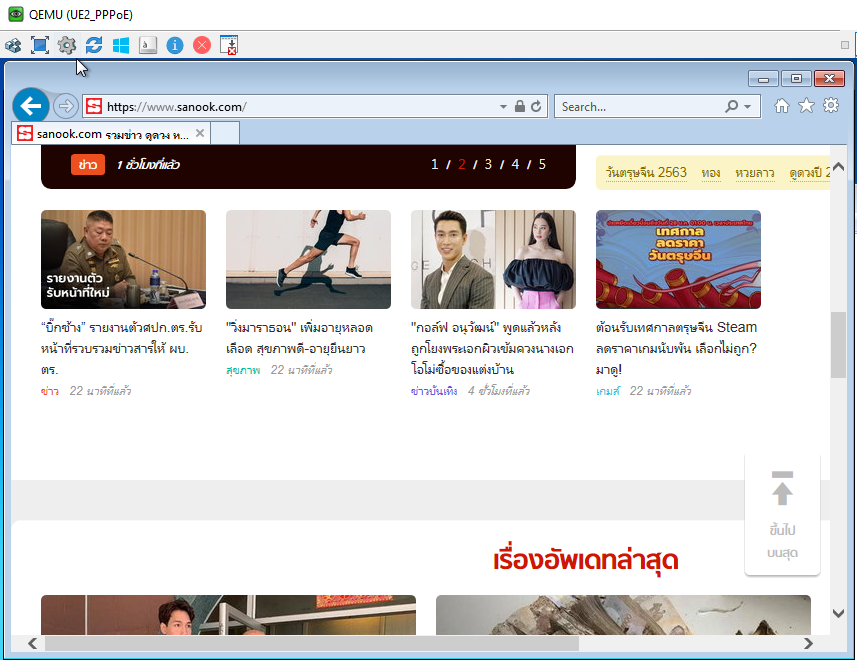
IPoE Client ทดสอบออก Internet

16. PPPoE Client Authentication และทดสอบออก Internet
PPPoE ในการ Authentication จะไม่เหมือน IPoE ต้องมีการเซ็ต Interface เพิ่มเติม โดยเข้าไปที่ Internet and Sharing Center แล้วคลิก Set up a new connection or netowrk เลือก Connect to the Internet ตามรูปภาพ
เลือก Create New Connection -> Broadband (PPPoE) -> ใส่ Username/Password ที่สร้างไว้ใน Tek Radius (bnet1@abc.com/abc1234) กด Connect

PPPoE เมื่อ Connect สำเร็จแล้ว มาเช็ค Status ตามรูป

PPPoE Client ทดสอบออก Internet
17. NOKIA BNG แสดงสถานะ IPoE/PPPoE session และสถานะการแจก IP ของ DHCP.
สถานะ IPoE/PPPoE session จะมี sla-profile กับ sub-profile ที่ได้มาจาก Radius ด้วย* IP ที่ Client ได้กับ ที่แสดงผล หรือ Capture อาจเป็นคนละ IP เนื่องจากผมเทสและเก็บผลหลายครั้งจึงทำให้ผลแตกต่างกัน
A:BNG# show service active-subscribers

===============================================================================
Active Subscribers
===============================================================================
-------------------------------------------------------------------------------
Subscriber 50:01:00:0a:00:00|1/1/5:20|1 (SUB-PPPOE-10M)
-------------------------------------------------------------------------------
-------------------------------------------------------------------------------
(1) SLA Profile Instance sap:1/1/5:20 - sla:SLA-PPPOE-10M
-------------------------------------------------------------------------------
IP Address
                MAC Address          Session        Origin       Svc        Fwd
-------------------------------------------------------------------------------
172.16.2.2
                50:01:00:0a:00:00    PPP 1          IPCP         100        Y
-------------------------------------------------------------------------------

-------------------------------------------------------------------------------
Subscriber 50:01:00:0b:00:00|1/1/5:10 (SUB-IPOE-PKG-1)
-------------------------------------------------------------------------------
-------------------------------------------------------------------------------
(1) SLA Profile Instance sap:1/1/5:10 - sla:SLA-IPOE-PKG-1
-------------------------------------------------------------------------------
IP Address
                MAC Address          Session        Origin       Svc        Fwd
-------------------------------------------------------------------------------
172.16.1.2
                50:01:00:0b:00:00    N/A            DHCP         100        Y
-------------------------------------------------------------------------------

-------------------------------------------------------------------------------
Number of active subscribers : 2
===============================================================================
A:BNG#
A:BNG# show router 100 dhcp local-dhcp-server "DHCP-SERVER-IPOE" leases

===============================================================================
Leases for DHCP server DHCP-SERVER-IPOE router 100
===============================================================================
IP Address      Lease State       Mac Address       Remaining   Clnt  Fail
  PPP user name/Opt82 Circuit Id                    LifeTime    Type  Ctrl
  User-db/Sticky-lease Hostname
-------------------------------------------------------------------------------
172.16.1.2      stable            50:01:00:0b:00:00 9d23h56m    dhcp  local

-------------------------------------------------------------------------------
1 leases found
===============================================================================
A:BNG# show router 100 dhcp local-dhcp-server "DHCP-SERVER-PPPOE" leases

===============================================================================
Leases for DHCP server DHCP-SERVER-PPPOE router 100
===============================================================================
IP Address      Lease State       Mac Address       Remaining   Clnt  Fail
  PPP user name/Opt82 Circuit Id                    LifeTime    Type  Ctrl
  User-db/Sticky-lease Hostname
-------------------------------------------------------------------------------
172.16.2.2      stable            50:01:00:0a:00:00 0h49m59s    ppp   local
  bnet1@abc.com
-------------------------------------------------------------------------------
1 leases found
===============================================================================
A:BNG#
18. ผล Capture Traffic IPoE
IPoE Client Capture file: https://1drv.ms/u/s!AtVkTJ4icW0Xl25bqVZhGEbxCG9w?e=7ZMMce
IPoE Radius Capture file: https://1drv.ms/u/s!AtVkTJ4icW0Xl201KbyjI6h5FRDA?e=hVQKWF

19. ผล Capture Traffic PPPoE
PPPoE Client Capture file: https://1drv.ms/u/s!AtVkTJ4icW0Xl2m9BoG4hDZd7qQK?e=qnvmt2
20 Version
Nokia 7750SR version TiMOS-C-16.0.R5Cisco3725 Version 12.4(15)T14
Juniper vSRX firefly-perimeter version 12.1X47-D15.4
Juniper vMX version 14.1R1.10
Juniper Olive version 12.1R1.9
eNSP version 1.2.00.510 V100R002C00
TekRADIUS LT version 5.5.3.0
แล็บนี้ก็มีเพียงเท่านี้ครับ
แล็บนี้ยังสามารถปรับปรุงได้อีกเยอะเช่น BNG Redundancy และฟังก์ชั่นอื่นๆ, ใช้ Linux FreeRadius แทน TekRADIUS. ทำ Radius Redundancy, Optimize Firewall Policy, ใช้ Router ทำ NAT แทน NAT-PC, ส่วน ISP Transmission จะเห็นว่าในนี้เป็น MPLS ผืนเดียวแต่ถ้า Router เป็นหลักร้อยหลักพันตัว จำเป็นทำเป็นหลายผืน เพื่อ Optimize Network รวมถึงการปรับปรุง L2VPN ให้เป็น Hierarchy เช่น H-VPLS หรือทำ Multi-Segment VLL. รวมไปถึง Pseudowire Redundancy และ LSP path protection. ไว้เจอกันแล็บหน้าครับ